Documentation technique PDF
RE7CV11BU
UGS : 8ac6e8114d50
Catégorie : Schneider
asymmetrical flashing relay - 0.05..1 s - 24 V AC DC - 1OC
Spécificités essentielles
Produits associés
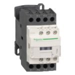
 Quick ViewDisjoncteurs modulaires sur rail MCB: Acti9 IC60
A9F77416 – Disjoncteur miniature 4P 16 A courbe C (Acti9 iC60N)
- Quick View
- Quick View


Options et accessoires compatibles
Autres produits associés

Description du produit
Référence :
RE7CV11BU Marque : Schneider Disponibilité : En Stock
Caractéristiques Techniques du produit
- RE7CV11BU (35 806 03)
- Characteristics
- asymmetrical flashing relay - 0.05..1 s - 24 V AC DC
- - 1OC
- Main
- Range of product Zelio Time
- Product or component type Industrial timing relay
- Component name RE7
- Time delay type L
- Li
- Lt
- Time delay range 0.05 s...300 h
- Complementary
- Discrete output type Relay
- Contacts material 90/10 silver nickel contacts
- Width pitch dimension 22.5 mm
- [Us] rated supply voltage 110...240 V AC at 50/60 Hz
- 24 V AC/DC at 50/60 Hz
- 42...48 V AC/DC at 50/60 Hz
- Voltage range 0.85...1.1 Us
- Connections - terminals Screw terminals, clamping capacity: 2 x 1.5 mm² flexible with cable end
- Screw terminals, clamping capacity: 2 x 2.5 mm² flexible without cable end
- Tightening torque 0.6...1.1 N.m
- Setting accuracy of time delay +/- 10 % of full scale
- Repeat accuracy +/- 0.2 %
- Temperature drift < 0.07 %/°C
- Voltage drift < 0.2 %/V
- Minimum pulse duration 20 ms
- Reset time 50 ms
- Maximum switching voltage 250 V AC/DC
- Mechanical durability 20000000 cycles
- [Ith] conventional free air thermal current 8 A
- [Ie] rated operational current <= 2 A DC-13 24 V at 70 °C conforming to IEC 60947-5-1/1991/VDE 0660
- <= 3 A AC-15 at 70 °C conforming to IEC 60947-5-1/1991/VDE 0660
- <= 0.1 A DC-13 250 V at 70 °C conforming to IEC 60947-5-1/1991/VDE 0660
- <= 0.2 A DC-13 115 V at 70 °C conforming to IEC 60947-5-1/1991/VDE 0660
- Minimum switching capacity 12 V / 10 mA
- Input voltage < 60 V X1Z2 terminal(s)
- < 60 V X2Z2 terminal(s)
- Maximum switching current 1 mA X1Z2 terminal(s)
- 1 mA X2Z2 terminal(s)
- Input compatibility 3/4 wires sensors PNP/NPN without internal load, cable length: <= 50 m X1Z2
- terminal(s)
- 3/4 wires sensors PNP/NPN without internal load, cable length: <= 50 m X2Z2
- terminal(s)
- Potentiometer characteristic Linear 47 kOhm (+/- 20 %), 0.2 W, cable length: <= 25 m Z1Z2terminal(s) Marking CE Overvoltage category III conforming to IEC 60664-1 [Ui] rated insulation voltage 250 V between contact circuit and control inputs IEC certified 250 V between contact circuit and power supply IEC certified 300 V between contact circuit and control inputs CSA certified 300 V between contact circuit and power supply CSA certified Supply disconnection value > 0.1 Uc
- Operating position Any position without derating
- 1 / 6
- The information provided in this documentation contains general descriptions and/or technical characteristics of the performance of the products contained herein.
- This documentation is not intended as a substitute for and is not to be used for determining suitability or reliability of these products for specific user applications.
- It is the duty of any such user or integrator to perform the appropriate and complete risk analysis, evaluation and testing of the products with respect to the relevant specific application or use thereof.
- Neither Schneider Electric Industries SAS nor any of its affiliates or subsidiaries shall be responsible or liable for misuse of the information contained herein.
- Surge withstand 2 kV conforming to IEC 61000-4-5 level 3
- Power consumption in VA 0.7 VA 24 V
- 1.6 VA 48 V
- 1.8 VA 110 V
- 8.5 VA 240 V
- Power consumption in W 0.5 W 24 V
- 1.2 W 48 V
- Terminal description (15-16-18)OC_OFF
- (B1-A2)CO
- ALT
- Height 78 mm
- Width 22.5 mm
- Depth 80 mm
- Product weight 0.15 kg
- Environment
- immunity to microbreaks 3 ms
- standards EN/IEC 61812-1
- product certifications CSA
- GL
- UL
- ambient air temperature for storage -40...85 °C
- ambient air temperature for operation -20...60 °C
- relative humidity 15...85 % (3K3) conforming to IEC 60721-3-3
- vibration resistance 0.35 mm (f = 10...55 Hz) conforming to IEC 60068-2-6
- shock resistance 15 gn for 11 ms conforming to IEC 60068-2-27
- IP degree of protection IP20 (terminals)
- IP50 (housing)
- pollution degree 3 conforming to IEC 60664-1
- dielectric strength 2.5 kV
- non-dissipating shock wave 4.8 kV
- resistance to electrostatic discharge 6 kV (in contact) conforming to IEC 61000-4-2 level 3
- 8 kV (in air) conforming to IEC 61000-4-2 level 3
- resistance to electromagnetic fields 10 V/m conforming to IEC 61000-4-3 level 3
- resistance to fast transients 2 kV conforming to IEC 61000-4-4 level 3
- disturbance radiated/conducted CISPR 11 group 1 - class A
- CISPR 22 - class A
- Width 22.5 mm
- Rail Mounting
- Screw Fixing
- 2 / 6
- Internal Wiring Diagram
- Recommended Application Wiring Diagram
- Selection of Starting Phase
- 1 Supply
- 2 12…48 V
- 3 24 V
- 6 Start during the On-delay period: X2, Z2 linked.Start during the Off-delay period: X2, Z2 not linked.
- Control of Several Relays
- Control of several relays with a single external control contact
- Connection of an External Control Contact Without Using Terminal Z2
- Direct current supply only.
- It is advisable to follow the recommended wiring schemes detailed above if the restrictions given are taken into account.
- Direct current supply only.
- It is advisable to follow the recommended wiring schemes detailed above if the restrictions given are taken into account.
- 3 / 6
- Connection 3-Wire NPN or PNP Sensor
- Connection 3-Wire NPN or PNP Sensor Without Using Terminal Z2
- Connection NPN
- It is advisable to follow the recommended wiring schemes detailed above if the restrictions given are taken into account.
- Connection PNP
- It is advisable to follow the recommended wiring schemes detailed above if the restrictions given are taken into account.
- Connection of Potentiometer
- 7 Off-delay adjustment (tr) (contact 15/16 closed).
- 8 On-delay adjustment (ta) (contact 15/18 closed).
- Connection Precautions
- WARNING
- UNEXPECTED EQUIPMENT OPERATION
- No galvanic isolation between supply terminals and control inputs.
- Failure to follow these instructions can result in death, serious injury, or equipment damage.
- Performance Curves
- A.C. Load Curve 1
- Electrical durability of contacts on resistive loading millions of operating cycles
- 4 / 6
- X Current broken in A
- Y Millions of operating cycles
- A.C. Load Curve 2
- Reduction factor k for inductive loads (applies to values taken from durability curve 1).
- X Power factor on breaking (cos ϕ)
- Y Reduction factor k
- Example: An LC1-F185 contactor supplied with 115 V/50 Hz for a consumption of 55 VA or a current consumption equal to 0.1 A and
- cos ϕ = 0.3. For 0.1 A, curve 1 indicates a durability of approximately 1.5 million operating cycles. As the load is inductive, it is
- necessary to apply a reduction coefficient k to this number of cycles as indicated by curve 2. For cos ϕ = 0.3: k = 0.6 The electrical
- 6
- durability therefore becomes:1.5 10 operating cycles x 0.6 = 900 000 operating cycles.
- D. C. Load Limit Curve
- X Current in A
- Y Voltage in V
- 1 L/R = 20 ms
- 2 L/R with load protection diode
- 3 Resistive load
- Function L : Asymmetrical Flasher Relay (Starting Pulse Off)
- Description
- Repetitive cycle comprises of two, independently adjustable timing periods Ta and Tr. Each timing period corresponds to a different
- state of the output R.
- Function: 1 Output
- 5 / 6
- Function Li : Asymmetrical Flasher Relay (Starting Pulse On)
- Description
- Repetitive cycle comprises of two, independently adjustable timing periods Ta and Tr. Each timing period corresponds to a different
- state of the output R.
- Function: 1 Output
- Function Lt: Asymmetrical Flashing with Partial Stop of Timing
- Description
- Repetitive cycle comprises of two, independently adjustable timing periods Ta and Tr. Each timing period corresponds to a different
- state of the output R.
- Gate control contact G can be operated to partially stop timing periods Ta and Tr.
- Function: 1 Output
- Tr = t1 + t2 + ...
- Ta = t’1 + t’2 +...
- Legend
- Relay de-energised
- Relay energised
- Output open
- Output closed
- C Control contact
- G Gate
- R Relay or solid state output
- R1/R22 timed outputs
- R2 The second output is instantaneous if the right position is selected
- inst.
- T Timing period
- Ta - Adjustable On-delay
- Tr - Adjustable Off-delay
- U Supply
- 6 / 6
Produits Similaires
Produits similaires


Produits récemment consultés
Aucun produit récemment consulté à afficher