Documentation technique PDF
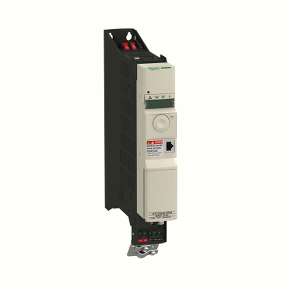
ATV32H037N4
UGS : 384e0be51753
Catégorie : Schneider
Frekvensomvandlare 0.37 kw - 400 V - 3-fas - med kylfläns
Spécificités essentielles
Produits associés
 Quick ViewDisjoncteurs modulaires sur rail MCB: Acti9 IC60
A9F77416 – Disjoncteur miniature 4P 16 A courbe C (Acti9 iC60N)
- Quick View
- Quick View


Options et accessoires compatibles
Autres produits associés
-
MGU3.411.30
Lire la suite AperçuConnectez-vous pour commander -
A9F74250
Lire la suite AperçuConnectez-vous pour commander -
AR1MC011
Lire la suite AperçuConnectez-vous pour commander -
XUX0AKSAT16T
Lire la suite AperçuConnectez-vous pour commander -
ABL6TS100U
Lire la suite AperçuConnectez-vous pour commander


Description du produit
Référence :
ATV32H037N4 Marque : Schneider Disponibilité : En Stock
Caractéristiques Techniques du produit
- ATV32H037N4
- Egenskaper
- Frekvensomvandlare 0.37 kw - 400 V - 3-fas - med
- kylfläns
- Huvudegenskaper
- Produktområde Altivar 32
- Produkt Frekvensomvandlare
- Produktdestination Asynkronmotorer
- Synkronmotorer
- Specifik produktanvändning Komplexa maskiner
- Tillgänglig funktion -
- Ihopmonteringssätt Med kylfläns
- Komponentnamn ATV32
- EMC-filter Klass C2 EMC filter inbyggt
- Nätverkets antal faser 3 fas
- [Us] matningsspänning 380...500 V - 15...10 %
- Matningsspänningsgränser 323...550 V
- Frekvens på matningsspänning 50...60 Hz - 5...5 %
- Nätverksfrekvens 47.5...63 Hz
- Motoreffekt kW 0.37 kW 380...500 V
- Motoreffekt hp 0.5 hp 380...500 V
- Kompletterande
- Linjeström 1.6 A 500 V 3 fas 0.37 kW 0.5 hp
- 2.1 A 380 V 3 fas 0.37 kW 0.5 hp
- Skenbar effekt 1.4 kVA 500 V 3 fas 0.37 kW 0.5 hp
- Kortslutningsström Ik3 (Isc) <= 5 kA 3 fas
- Nominell utgångsström 1.5 A 4 kHz 500 V 0.37 kW 0.5 hp
- Maximal transient ström 2.3 A 60 s 0.37 kW 0.5 hp
- Utgångsfrekvens 0.0005...0.599 kHz
- Nominell växlingsfrekvens 4 kHz
- Switchfrekvens 2...16 kHz Justerbar
- Hastighetsområde 1...100 asynkronmotor i öppen slinga läge
- Hastighetsnoggrannhet +/- 10 % av nominell eftersläpning 0.2 Tn to Tn
- Momentnoggrannhet +/- 15 %
- Transient övermoment 170...200 %
- Vridmoment inbromsning <= 170 % with braking resistor
- Asynkronmotor kontrollprofil Spänning/frekvensförhållande, 2 punkter
- Spänning/frekvensförhållande, 5 punkter
- Flux vektor kontroll utan pulsgivare - energispar pump och fläkt
- Flux vektor kontroll utan pulsgivare, standard
- Spänning/frekvensförhållande - energispar, kvadratiskt U/f
- Synkronmotor kontrollprofil Vektorstyrning utan sensor
- Reglering slinga Justerbar PID regulator
- Kompensation av eftersläpning på motorn Automatisk oavsett belastning
- Inte tillgänglig i spänning / frekvensförhållande (2 eller 5 poäng)
- Justerbar 0 ... 300%
- Indikeringslampa 1 LED röd enhetsspänning
- 1 LED grön CANopen run
- 1 LED röd CANopen fel
- 1 LED röd enhetsfel
- Utspänning <= matningsspänning
- Ljudnivå 43 dB 86/188/EEC
- Isolation Elektrisk mellan kraft och manöver
- 1 / 8
- Informationen i denna dokumentation innehåller allmänna beskrivningar och / eller tekniska egenskaper prestanda för produkter som ingår häri.
- Denna dokumentation är inte avsedd som en ersättning för och ska inte användas för att avgöra lämplighet eller tillförlitlighet hos dessa produkter för specifika användargrupper tillämpningar.
- Det är en plikt för en sådan användare eller integratör att utföra lämpliga och kompletta riskanalys, utvärdering och provning av produkterna med avseende på de relevanta särskilda program eller användning.
- Varken Schneider Electric Industries SAS eller något av dess dotterbolag eller dotterbolag skall vara ansvariga för missbruk av informationen häri.
- Elektrisk anslutning Skruvplint 0.5...1.5 mm² AWG 18...AWG 14 control
- Löstagbara skruvplintar 1.5...2.5 mm² AWG 14...AWG 12 motor/bromsmotstånd
- Skruvplint 1.5...4 mm² AWG 14...AWG 10 kraftmatning
- Åtdragningsmoment 0.5 N.m 4.4 lb/ft control
- 0.7 N.m 7.1 lb/ft motor/bromsmotstånd
- 0.6 N.m 5.3 lb/ft kraftmatning
- Matning Intern matning för referenspotentiometer (1-10 kOhm) 10.5 V DC +/- 5 % <= 10 mA
- överbelastning och kortslutningsskydd
- Analoga ingångar 3
- Analog ingång Spänning AI1 0...10 V DC 30000 Ohm 10 bitar
- Bipoläär differentialspänning AI2 +/- 10 V DC 30000 Ohm 10 bitar
- Ström AI3 0 ... 20 mA (eller 4-20 mA, x-20 mA, 20-x mA eller andra mönster av
- konfiguration) 250 Ohm 10 bitar
- Samplingslängd 2 ms AI1, AI2, AI3 analog
- 2 ms AO1 analog
- Svarstid 8 ms +/- 0.7 ms LI1...LI6 logik
- 2 ms R1A, R1B, R1C relä
- 2 ms R2A, R2C relä
- Noggrannhet +/- 0.2 % AI1, AI2, AI3 för en temperatur av -10...60 °C
- +/- 0.5 % AI1, AI2, AI3 för en temperatur av 25 °C
- +/- 1 % AO1 för en temperatur av 25 °C
- +/- 2 % AO1 för en temperatur av -10...60 °C
- Linjärt fel +/- 0.2...0.5 % av max värde AI1, AI2, AI3
- +/- 0.3 % AO1
- Analoga utgångar 1
- Analog utgångstyp Software-configurable current AO1 0...20 mA 800 Ohm 10 bits
- Software-configurable voltage AO1 0...10 V 470 Ohm 10 bits
- Digitala utgångar 3
- Diskret utgångstyp Konfigurerbar relälogik R1A, R1B, R1C NO/NC 100000 cycles
- Konfigurerbar relälogik R2A, R2B Nej 100000 cycles
- Logik LO
- Minsta brytström 5 mA 24 V DC konfigurerbar relälogik
- Maximal brytström 3 A 250 V AC resistive (cos phi = 1 R1
- 4 A 30 V DC resistive (cos phi = 1 R1
- 2 A 250 V AC inductive (cos phi = 0.4 R1, R2
- 2 A 30 V DC inductive (cos phi = 0.4 R1, R2
- 5 A 250 V AC resistive (cos phi = 1 R2
- 5 A 30 V DC resistive (cos phi = 1 R2
- Digital ingångsantal 7
- Digital ingångstyp Programmerbar (sink/source) LI1...LI4 24...30 V DC PLC nivå 1
- Programmerbar som pulsingång 20 kpps LI5 24...30 V DC PLC nivå 1
- Valbar PTC probe LI6 24...30 V DC
- Safe torque off STO 24...30 V DC 1500 Ohm
- Digital ingångslogik Positiv logik (source) LI1...LI6 < 5 V > 11 V
- Negativ logik (sink) LI1...LI6 > 19 V < 13 V
- Accelerations- och retardationsramper S
- U
- CUS
- Retardationsramp automatiskt stopp DC-injicering
- Retardationsramp anpassning
- Linjär
- Rampomkoppling
- Bromsning till stillastående By DC injection
- Skyddstyp Fasavbrott på ingång omvandlare
- Överström mellan utgångsfaserna och jord omvandlare
- Överhettningsskydd omvandlare
- Kortslutning mellan motorfaserna omvandlare
- Termiskt skydd omvandlare
- Protokoll CANopen
- Modbus
- Typ av kontakt 1 RJ45 Modbus/CANopen på framsidan
- Fysiskt interface 2-tråds RS 485 Modbus
- Sändningsram RTU Modbus
- Typ av polarisation Ingen impedans Modbus
- Antal adresser 1...247 Modbus
- 1...127 CANopen
- Åtkomstmetod Slav CANopen
- 2 / 8
- Elektromagnetisk kompabilitet 1.2/50 µs - 8/20 µs immunitet test nivå 3 IEC 61000-4-5
- Elektrisk snabb transient / burst immunitet test nivå 4 IEC 61000-4-4
- Elektrostatisk urladdning immunitet test nivå 3 IEC 61000-4-2
- Strålade radiofrekventa elektromagnetiska fält immunitet test nivå 3 IEC 61000-4-3
- Genomfört radiofrekvens immunitet test nivå 3 IEC 61000-4-6
- Spänningsdippar och avbrottsokänslighets test IEC 61000-4-11
- Bredd 45 mm
- Höjd 325 mm
- Djup 245 mm
- Vikt 2.5 kg
- Optionskort Kommunikationskort CANopen daisy chain
- Kommunikationskort öppen CANopen
- Kommunikationskort DeviceNet
- Kommunikationskort Ethernet/IP
- Kommunikationskort Profibus DP V1
- Funktionalitet MID
- Specifik tillämpning Andra applikationer
- Miljödokumentation
- produktstandard EN 55011 klass A grupp 1
- EN 61800-3 miljöer 1 kategori C2
- EN 61800-3 miljöer 2 kategori C2
- EN/IEC 61800-3
- EN/IEC 61800-5-1
- certifiering CSA
- C-Tick
- GOST
- NOM 117
- UL
- märkning CE
- föroreningsgrad 2 EN/IEC 61800-5-1
- IP-kapslingsklass IP20 EN/IEC 61800-5-1
- vibrationsbeständighet 1 gn 13...200 Hz EN/IEC 60068-2-6
- 1.5 mm peak till peak 3...13 Hz EN/IEC 60068-2-6
- shockbeständighet 15 gn 11 ms EN/IEC 60068-2-27
- relativ fuktighet 5...95 % utan kondens IEC 60068-2-3
- 5...95 % utan droppande vatten IEC 60068-2-3
- omgivningstemeperatur vid drift -10...50 °C utan nedklassning
- 50...60 °C med nedklassningsfaktor
- omgivande lufttemperatur för lagring -25...70 °C
- höjd över havet <= 1000 m utan nedklassning
- 1000...3000 m med strömnedklassning 1 % per 100 m
- arbetsläge Vertikalt +/- 10 grader
- Hållbarhetsinformation
- Erbjudandets hållbarhetsstatus Green Premium produkt
- RoHS (datumkod: ÅÅVV) Kompatibel -sedan 1007 - Schneider Electric declaration of conformity
- REACh Produkten innehåller inte SVHC över tröskelvärdet
- Miljöprofil Tillgänglig
- Information av uttjänta produkter Tillgänglig
- Contractual warranty
- Warranty period 18 months
- Size A
- Dimensions
- 3 / 8
- Mounting and Clearance
- (1) Minimum value corresponding to thermal constraints. A 150 mm clearance may help to connect the ground.
- (2) Optional GV2 circuit-breaker
- Option: Protection Device, GV2 circuit-breaker
- The drive is prepared to be equipped with an optional GV2 circuit-breaker.
- The GV2 circuit-breaker is directly mounted on the drive. Mechanical and electrical link are made using the optional adapter. The
- options are supplied with detailed mounting instruction sheet.
- NOTE: The product overall dimension, including GV2 adapter and EMC plate mounted, becomes 424 mm (16.7 in.)
- 4 / 8
- (1) Ground screw (HS type 2 - 5x12)
- Connection Diagrams
- Single or Three-phase Power Supply - Diagram with Line Contactor
- Connection diagrams conforming to standards EN 954-1 category 1 and IEC/EN 61508 capacity SIL1, stopping category 0 in
- accordance with standard IEC/EN 60204-1.
- (1) Line choke (if used)
- (3) Fault relay contacts, for remote signaling of drive status
- Single or Three-phase Power Supply - Diagram with Switch Disconnect
- Connection diagrams conforming to standards EN 954-1 category 1 and IEC/EN 61508 capacity SIL1, stopping category 0 in
- accordance with standard IEC/EN 60204-1.
- (1) Line choke (if used)
- (3) Fault relay contacts, for remote signaling of drive status
- Diagram with Preventa Safety Module (Safe Torque Off Function)
- Connection diagrams conforming to standards EN 954-1 category 3 and IEC/EN 61508 capacity SIL2, stopping category 0 in
- accordance with standard IEC/EN 60204-1.
- When the emergency stop is activated, the drive power supply is cut immediately and the motor stops in freewheel, according to
- category 0 of standard IEC/EN 60204-1.
- A contact on the Preventa XPS AC module must be inserted in the brake control circuit to engage it safely when the STO (Safe Torque
- Off) safety function is activated.
- 5 / 8
- (1) Line choke (if used)
- (2) It is essential to connect the shielding to the ground.
- (3) Fault relay contacts, for remote signaling of drive status
- The STO safety function integrated into the product can be used to implement an "EMERGENCY STOP" (IEC 60204-1) for category 0
- stops.
- With an additional, approved EMERGENCY STOP module, it is also possible to implement category 1 stops.
- STO function
- The STO safety function is triggered via 2 redundant inputs. The circuits of the two inputs must be separate so that there are always
- two channels. The switching process must be simultaneous for both inputs (offset < 1 s).
- The power stage is disabled and an error message is generated. The motor can no longer generate torque and coasts down without
- braking. A restart is possible after resetting the error message with a "Fault Reset".
- The power stage is disabled and an error message is generated if only one of the two inputs is switched off or if the time offset is too
- great. This error message can only be reset by switching off the product.
- Diagram without Preventa Safety Module
- Connection diagrams conforming to standards EN 954-1 category 2 and IEC/EN 61508 capacity SIL1, stopping category 0 in
- accordance with standard IEC/EN 60204-1.
- The connection diagram below is suitable for use with machines with a short freewheel stop time (machines with low inertia or high
- resistive torque).
- When the emergency stop is activated, the drive power supply is cut immediately and the motor stops in freewheel, according to
- category 0 of standard IEC/EN 60204-1.
- (1) Line choke (if used)
- (2) It is essential to connect the shielding to the ground.
- (3) Fault relay contacts, for remote signaling of drive status
- The STO safety function integrated into the product can be used to implement an "EMERGENCY STOP" (IEC 60204-1) for category 0
- stops.
- Control Connection Diagram in Source Mode
- 6 / 8
- (1) Reference potentiometer SZ1RV1202 (2.2 kΩ) or similar (10 kΩ maximum)
- Derating Curves
- Derating curve for the nominal drive current (In) as a function of temperature and switching frequency.
- X Switching frequency
- Above 4 kHz, the drive will reduce the switching frequency automatically in the event of an excessive temperature rise.
- Sink / Source Switch Configuration (SW1)
- The logic input switch (SW1) is used to adapt the operation of the logic inputs to the technology of the programmable controller outputs.
- Switch SW1 set to “Source” position
- Switch SW1 set to “Source” position and use of an external power supply for the LIs
- Switch SW1 set to “Sink Int” position
- Switch SW1 set to “Sink Ext” position
- 7 / 8
- 8 / 8