ATV71E5D55N4
Caractéristiques
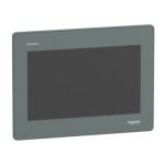
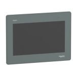
variateur de vitesse ATV71
55 kW - 480 V - avec
Principales
Gamme de produits Altivar 71
Type de produit ou de composant Variateur de vitesse
Application spécifique du produit Machines complexes haute puissance
Nom de composant ATV71
Puissance moteur kW 55 kW
Puissance moteur hp 75 hp
[Us] tension assignée 380...480 V (
15...10 %)
d'alimentation
Nombre de phases réseau Triphasé
Courant de ligne 101 A pour 480 V
120 A pour 380 V
Filtre CEM Filtre CEM classe A
Intégré
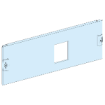
Variante de construction Intégré avec l'interrupteur
sectionneur Vario
Variante Avec platine CEM
Puissance apparente 79 kVA à 380 V
Courant transitoire maximum 174 A pour 60 s
191 A pour 2 s
Fréquence de sortie du variateur 0...500 Hz
de vitesse
Fréquence de commutation 2,5 kHz
nominale
Fréquence de commutation 1...16 kHz réglable
2,5...16kHz avec facteur de correction
Profil de commande pour moteur Système ENA (adaptation énergétique) pour
asynchrone charges déséquilibrées
Contrôle vectoriel du flux de courant (FVC) avec
capteur (vecteur de courant)
Ctrl. vectoriel flux courant sans capteur (SFVC)
(vecteur tension ou courant)
Rapport tension/fréquence(2 ou 5 points)
Type de polarisation Aucune impédance pour Modbus
Complémentaires
Destination du produit Moteurs asynchrones
Moteurs synchrones
Limites de la tension d'alimentation 323...528 V
Fréquence d'alimentation 50...60 Hz +/
5 %
Limites de fréquence réseau 47.5...63 Hz
Lsc présumé de ligne

 Quick ViewDisjoncteurs modulaires sur rail MCB: Acti9 IC60