


-
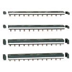
 Quick ViewLire la suiteDisjoncteurs modulaires sur rail MCB: Acti9 IC60
A9F77416 – Disjoncteur 4P Courbe C Schneider Electric
-
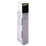
 Quick ViewAjouter au panier
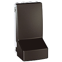
 -
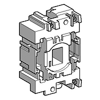
 Quick ViewAjouter au panier
Nos marques
Produits récemment consultés

Trouvez tout ce dont vous avez besoin dans notre catalogue

Livraison adaptée à vos besoins
Nos solutions de livraison fiables et rapides facilitent votre quotidien

Recevez une assistance technique de spécialistes pour soutenir vos projets