

ATV32HU30N4
UGS : d72b01012f88
Catégorie : Schneider
variable speed drive ATV32 - 3 kw - 400 V - 3 phase - with heat sink
Caractéristiques principales
Produits associés

Options et accessoires compatibles
Autres produits associés
Voir tous les produits →-

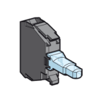
Contrôle, Relais et Signalisation
ZBVB4 Schneider Electric : bloc lumineux LED rouge 24V★★★★½Prix sur demandeEn stock
Voir le produit -
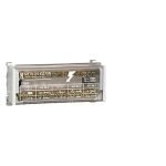
Disjoncteurs forte puissance (boitier moulé et ouvert)
LV431534★★★★½Prix sur demandeEn stock
Voir le produit -
-
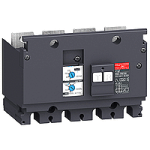
Contacteurs, sectionneurs, relais multifonctions
LAD21★★★★½Prix sur demandeEn stock
Voir le produit -
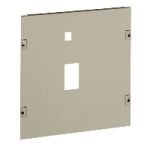
Canalisations électriques préfabriquées
KSA630DMCL4CF★★★★½Prix sur demandeEn stock
Voir le produit


Description du produit
Schneider
Réf. d72b01012f88
Noter cette article
Référence :
ATV32HU30N4
Marque : Schneider
Disponibilité : En Stock
Caractéristiques Techniques du produit
ATV32HU30N4
Characteristics
variable speed drive ATV32
3 kw - 400 V - 3 phase
- with heat sink
Main
Range of product Altivar 32
Product or component type Variable speed drive
Product destination Asynchronous motors
Synchronous motors
Product specific application Complex machines
Function available -
Assembly style With heat sink
Component name ATV32
EMC filter Class C2 EMC filter integrated
Network number of phases 3 phases
[Us] rated supply voltage 380...500 V
15...10 %
Supply voltage limits 323...550 V
Supply frequency 50...60 Hz
5...5 %
Network frequency 47.5...63 Hz
Motor power kW 3 kW 380...500 V
Complementary
Line current 11.1 A 380 V 3 phases 3 kW
8.4 A 500 V 3 phases 3 kW
Apparent power 7.3 kVA 500 V 3 phases 3 kW
Prospective line Isc <= 5 kA 3 phases
Nominal output current 7.1 A 4 kHz 500 V 3 kW
Maximum transient current 10.7 A 60 s 3 kW
Output frequency 0.0005...0.599 kHz
Nominal switching frequency 4 kHz
Switching frequency 2...16 kHz adjustable
Speed range 1...100 asynchronous motor in open
loop mode
Speed accuracy +/
10 % of nominal slip 0.2 Tn to Tn
Torque accuracy +/
15 %
Transient overtorque 170...200 %
Braking torque <= 170 % with braking resistor
Asynchronous motor control profile Voltage/frequency ratio, 2 points
Voltage/frequency ratio, 5 points
Flux vector control without sensor
Energy Saving, NoLoad law
Flux vector control without sensor, standard
Voltage/frequency ratio
Energy Saving, quadratic U/f
Synchronous motor control profile Vector control without sensor
Regulation loop Adjustable PID regulator
Motor slip compensation Automatic whatever the load
Not available in voltage/frequency ratio (2 or 5 points)
Adjustable 0...300 %
Local signalling 1 LED red drive voltage
1 LED green CANopen run
1 LED red CANopen error
1 LED red drive fault
Output voltage <= power supply voltage
Noise level 45 dB 86/188/EEC
Insulation Electrical between power and control
Electrical connection Screw terminal 0.5...1.5 mm² AWG 18...AWG 14 control
1 / 8
The information provided in this documentation contains general descriptions and/or technical characteristics of the performance of the products contained herein.
This documentation is not intended as a substitute for and is not to be used for determining suitability or reliability of these products for specific user applications.
It is the duty of any such user or integrator to perform the appropriate and complete risk analysis, evaluation and testing of the products with respect to the relevant specific application or use thereof.
Neither Schneider Electric Industries SAS nor any of its affiliates or subsidiaries shall be responsible or liable for misuse of the information contained herein.
Removable screw terminals 1.5...2.5 mm² AWG 14...AWG 12 motor/braking resistor
Screw terminal 1.5...4 mm² AWG 14...AWG 10 power supply
Tightening torque 0.5 N.m 4.4 lb/ft control
0.7 N.m 7.1 lb/ft motor/braking resistor
0.6 N.m 5.3 lb/ft power supply
Supply Internal supply for reference potentiometer (1 to 10 kOhm) 10.5 V DC +/
5 % <= 10
mA overload and short
circuit protection
Analogue input number 3
Analogue input type Voltage AI1 0...10 V DC 30000 Ohm 10 bits
Bipolar differential voltage AI2 +/
10 V DC 30000 Ohm 10 bits
Current AI3 0...20 mA (or 4
20 mA, x-20 mA, 20-x mA or other patterns by
configuration) 250 Ohm 10 bits
Sampling duration 2 ms AI1, AI2, AI3 analog
2 ms AO1 analog
Response time 8 ms +/
0.7 ms LI1...LI6 logic
2 ms R1A, R1B, R1C relay
2 ms R2A, R2C relay
Accuracy +/
0.2 % AI1, AI2, AI3 for a temperature of -10...60 °C
+/
0.5 % AI1, AI2, AI3 for a temperature of 25 °C
+/
1 % AO1 for a temperature of 25 °C
+/
2 % AO1 for a temperature of -10...60 °C
Linearity error +/
0.2...0.5 % of maximum value AI1, AI2, AI3
+/
0.3 % AO1
Analogue output number 1
Analogue output type Software
configurable current AO1 0...20 mA 800 Ohm 10 bits
Software
configurable voltage AO1 0...10 V 470 Ohm 10 bits
Discrete output number 3
Discrete output type Configurable relay logic R1A, R1B, R1C NO/NC 100000 cycles
Configurable relay logic R2A, R2B NO 100000 cycles
Logic LO
Minimum switching current 5 mA 24 V DC configurable relay logic
Maximum switching current 3 A 250 V AC resistive (cos phi = 1 R1
4 A 30 V DC resistive (cos phi = 1 R1
2 A 250 V AC inductive (cos phi = 0.4 R1, R2
2 A 30 V DC inductive (cos phi = 0.4 R1, R2
5 A 250 V AC resistive (cos phi = 1 R2
5 A 30 V DC resistive (cos phi = 1 R2
Discrete input number 7
Discrete input type Programmable (sink/source) LI1...LI4 24...30 V DC level 1 PLC
Programmable as pulse input 20 kpps LI5 24...30 V DC level 1 PLC
Switch
configurable PTC probe LI6 24...30 V DC
Safe torque off STO 24...30 V DC 1500 Ohm
Discrete input logic Positive logic (source) LI1...LI6 < 5 V > 11 V
Negative logic (sink) LI1...LI6 > 19 V < 13 V
Acceleration and deceleration ramps S
U
CUS
Deceleration ramp automatic stop DC injection
Deceleration ramp adaptation
Linear
Ramp switching
Braking to standstill By DC injection
Protection type Input phase breaks drive
Overcurrent between output phases and earth drive
Overheating protection drive
Short
circuit between motor phases drive
Thermal protection drive
Communication port protocol CANopen
Modbus
Type of connector 1 RJ45 Modbus/CANopen on front face
Physical interface 2
wire RS 485 Modbus
Transmission frame RTU Modbus
Type of polarization No impedance Modbus
Number of addresses 1...247 Modbus
1...127 CANopen
Method of access Slave CANopen
Electromagnetic compatibility 1.2/50 µs
8/20 µs surge immunity test level 3 IEC 61000-4-5
2 / 8
Electrical fast transient/burst immunity test level 4 IEC 61000
4-4
Electrostatic discharge immunity test level 3 IEC 61000
4-2
Radiated radio
frequency electromagnetic field immunity test level 3 IEC 61000-4-3
Conducted radio
frequency immunity test level 3 IEC 61000-4-6
Voltage dips and interruptions immunity test IEC 61000
4-11
Width 60 mm
Height 325 mm
Depth 245 mm
Product weight 3 kg
Option card Communication card CANopen daisy chain
Communication card CANopen open style
Communication card DeviceNet
Communication card Ethernet/IP
Communication card Profibus DP V1
Functionality Mid
Specific application Other applications
Environment
standards EN 55011 class A group 1
EN 61800
3 environments 1 category C2
EN 61800
3 environments 2 category C2
EN/IEC 61800
3
EN/IEC 61800
5-1
product certifications CSA
C
Tick
GOST
NOM 117
UL
marking CE
pollution degree 2 EN/IEC 61800
5-1
IP degree of protection IP20 EN/IEC 61800
5-1
vibration resistance 1 gn 13...200 Hz EN/IEC 60068
2-6
1.5 mm peak to peak 3...13 Hz EN/IEC 60068
2-6
shock resistance 15 gn 11 ms EN/IEC 60068
2-27
relative humidity 5...95 % without condensation IEC 60068
2-3
5...95 % without dripping water IEC 60068
2-3
ambient air temperature for operation
10...50 °C without derating
50...60 °C with derating factor
ambient air temperature for storage
25...70 °C
operating altitude <= 1000 m without derating
1000...3000 m with current derating 1 % per 100 m
operating position Vertical +/
10 degree
Offer Sustainability
Sustainable offer status Green Premium product
RoHS (date code
YYWW) Compliant - since 1007 - Schneider Electric declaration of conformity
REACh Reference not containing SVHC above the threshold
Product environmental profile Available
Product end of life instructions Available
Contractual warranty
Warranty period 18 months
Size B
Dimensions
3 / 8
Mounting and Clearance
(1) Minimum value corresponding to thermal constraints. A 150 mm clearance may help to connect the ground.
(2) Optional GV2 circuit
breaker
Option
Protection Device, GV2 circuit-breaker
The drive is prepared to be equipped with an optional GV2 circuit
breaker.
The GV2 circuit
breaker is directly mounted on the drive. Mechanical and electrical link are made using the optional adapter. The
options are supplied with detailed mounting instruction sheet.
NOTE
The product overall dimension, including GV2 adapter and EMC plate mounted, becomes 424 mm (16.7 in.)
4 / 8
(1) Ground screw (HS type 2
5x12)
Connection Diagrams
Single or Three
phase Power Supply - Diagram with Line Contactor
Connection diagrams conforming to standards EN 954
1 category 1 and IEC/EN 61508 capacity SIL1, stopping category 0 in
accordance with standard IEC/EN 60204
1.
(1) Line choke (if used)
(3) Fault relay contacts, for remote signaling of drive status
Single or Three
phase Power Supply - Diagram with Switch Disconnect
Connection diagrams conforming to standards EN 954
1 category 1 and IEC/EN 61508 capacity SIL1, stopping category 0 in
accordance with standard IEC/EN 60204
1.
(1) Line choke (if used)
(3) Fault relay contacts, for remote signaling of drive status
Diagram with Preventa Safety Module (Safe Torque Off Function)
Connection diagrams conforming to standards EN 954
1 category 3 and IEC/EN 61508 capacity SIL2, stopping category 0 in
accordance with standard IEC/EN 60204
1.
When the emergency stop is activated, the drive power supply is cut immediately and the motor stops in freewheel, according to
category 0 of standard IEC/EN 60204
1.
A contact on the Preventa XPS AC module must be inserted in the brake control circuit to engage it safely when the STO (Safe Torque
Off) safety function is activated.
5 / 8
(1) Line choke (if used)
(2) It is essential to connect the shielding to the ground.
(3) Fault relay contacts, for remote signaling of drive status
The STO safety function integrated into the product can be used to implement an "EMERGENCY STOP" (IEC 60204
1) for category 0
stops.
With an additional, approved EMERGENCY STOP module, it is also possible to implement category 1 stops.
STO function
The STO safety function is triggered via 2 redundant inputs. The circuits of the two inputs must be separate so that there are always
two channels. The switching process must be simultaneous for both inputs (offset < 1 s).
The power stage is disabled and an error message is generated. The motor can no longer generate torque and coasts down without
braking. A restart is possible after resetting the error message with a "Fault Reset".
The power stage is disabled and an error message is generated if only one of the two inputs is switched off or if the time offset is too
great. This error message can only be reset by switching off the product.
Diagram without Preventa Safety Module
Connection diagrams conforming to standards EN 954
1 category 2 and IEC/EN 61508 capacity SIL1, stopping category 0 in
accordance with standard IEC/EN 60204
1.
The connection diagram below is suitable for use with machines with a short freewheel stop time (machines with low inertia or high
resistive torque).
When the emergency stop is activated, the drive power supply is cut immediately and the motor stops in freewheel, according to
category 0 of standard IEC/EN 60204
1.
(1) Line choke (if used)
(2) It is essential to connect the shielding to the ground.
(3) Fault relay contacts, for remote signaling of drive status
The STO safety function integrated into the product can be used to implement an "EMERGENCY STOP" (IEC 60204
1) for category 0
stops.
Control Connection Diagram in Source Mode
6 / 8
(1) Reference potentiometer SZ1RV1202 (2.2 kΩ) or similar (10 kΩ maximum)
Derating Curves
Derating curve for the nominal drive current (In) as a function of temperature and switching frequency.
X Switching frequency
Above 4 kHz, the drive will reduce the switching frequency automatically in the event of an excessive temperature rise.
Sink / Source Switch Configuration (SW1)
The logic input switch (SW1) is used to adapt the operation of the logic inputs to the technology of the programmable controller outputs.
Switch SW1 set to
Switch SW1 set to
Switch SW1 set to
Switch SW1 set to
7 / 8
8 / 8
Produits Similaires
Produits similaires


Produits récemment consultés
Aucun produit récemment consulté à afficher