
 Quick ViewDisjoncteurs modulaires sur rail MCB: Acti9 IC60
A9F77416 – Disjoncteur miniature 4P 16 A courbe C (Acti9 iC60N)
- Quick View
- Quick View

Autres produits associés
Voir tous les produits →-
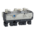
Disjoncteurs forte puissance (boitier moulé et ouvert)
LV431500★★★★½Prix sur demandeEn stock
Voir le produit -
Contacteurs, sectionneurs, relais multifonctions
LAD96061★★★★½Prix sur demandeEn stock
Voir le produit